Daikin Zone Controller Installation: A Comprehensive Guide
This guide details installing Daikin’s advanced zone controllers, offering innovative features for tailored comfort and flexibility; It covers safety, wiring, and troubleshooting procedures.
Understanding Daikin Zone Controllers
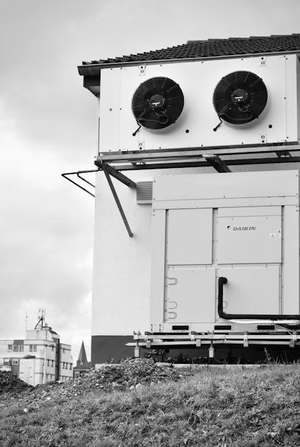
Daikin Zone Controllers represent a state-of-the-art approach to managing ducted air conditioning systems, allowing for precise temperature control in individual zones within a building. These controllers offer a significant upgrade over traditional systems, providing enhanced comfort and energy efficiency. They are designed to work seamlessly with Daikin ducted air conditioning units, enabling customized climate control to meet specific needs;
The core function of a Daikin Zone Controller is to regulate airflow to different areas, optimizing temperature and reducing energy waste. This is achieved through sophisticated programming and user-friendly interfaces. The controllers boast advanced design, offering flexibility in installation locations and a backlit display for easy operation. Understanding these controllers is crucial for maximizing the benefits of a Daikin ducted system, ensuring a comfortable and cost-effective indoor environment.
Models Available: BRC230Z4, BRC230Z8, BRC24Z4
Daikin offers a range of Zone Controllers to suit diverse needs, with the BRC230Z4, BRC230Z8, and BRC24Z4 being the primary models. These controllers differ in their features and capabilities, allowing for tailored system configuration; The BRC230Z4 is a foundational model, providing essential zoning functionality. The BRC230Z8 offers expanded features, potentially including more zones or advanced scheduling options.
The BRC24Z4 represents a further evolution, likely incorporating the latest technological advancements and enhanced user interfaces. Each model is designed for easy integration with Daikin ducted systems, ensuring optimal performance and control. Selecting the appropriate model depends on the complexity of the zoning requirements and the desired level of customization. Understanding the distinctions between these models is key to choosing the best solution for a specific installation.
Safety Precautions & Warnings
Prior to commencing installation, strict adherence to safety guidelines is paramount. Disconnect all power sources to the air conditioning system to prevent electrical shock. Installation should only be performed by qualified personnel familiar with electrical wiring and HVAC systems. Always verify the voltage compatibility between the controller and the system.
Exercise caution when handling wiring, ensuring connections are secure and properly insulated to mitigate fire hazards. Avoid installing the controller in damp or corrosive environments. Carefully read and understand the entire installation manual before beginning. Failure to follow these precautions could result in personal injury, property damage, or system malfunction. Always use appropriate personal protective equipment (PPE), including safety glasses and insulated gloves.
Required Tools and Accessories
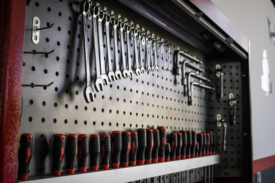
Successful installation necessitates a specific toolkit and supplementary components. Essential tools include a screwdriver set (Phillips and flathead), wire strippers, pliers, and a multimeter for voltage testing. A drill with appropriate bits is needed for mounting the controller securely. Accessories required are cable ties for neat wiring management, and potentially, a Daikin option KRCSO1-1 cut plug off lead for specific connections.
Black plastic wiring bushes, pre-installed on the controller box, are crucial for safe wire passage. Ensure you have sufficient wiring of the correct gauge for the system’s electrical requirements. Consider having a voltage tester readily available to confirm power is disconnected before working on wiring. Proper preparation with these tools and accessories streamlines the installation process and ensures a reliable outcome.
Installation Process
The installation involves mounting the controller, carefully reviewing the wiring diagram, and executing precise field wiring procedures for optimal system performance.
Mounting the Zone Controller
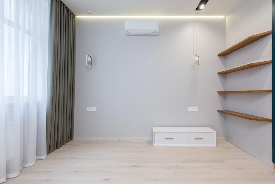
Selecting a suitable location is crucial for effective zone control. Daikin’s controllers boast an advanced design, granting flexibility in placement within the desired area. Ensure the chosen spot allows easy access for operation and future maintenance. The controller should be mounted securely to a wall, avoiding direct sunlight or sources of extreme temperature fluctuations.
Prior to mounting, verify the wall can support the controller’s weight. Use appropriate screws and anchors suitable for the wall material. Once positioned, carefully align the mounting holes and fasten the controller firmly. It’s essential to ensure the unit is level to guarantee accurate display readability and proper functionality. A stable and secure mounting prevents potential damage and ensures long-term reliability of the zone control system.
Wiring Diagram Overview
A thorough understanding of the wiring diagram is paramount before commencing any electrical connections. The diagram details the specific wiring configuration for your Daikin zone controller model (BRC230Z4, BRC230Z8, or BRC24Z4). It illustrates the connections between the controller, the main air conditioning unit, and any associated zone dampers.
Carefully identify each wire and its corresponding terminal on both the controller and the air conditioning system. Pay close attention to polarity and voltage requirements to prevent damage. The diagram will indicate the necessary wiring for power supply, communication signals, and zone control signals. Ensure all wiring complies with local electrical codes and regulations. Proper wiring is critical for the correct operation and safety of the entire zoned system.
Field Wiring Procedures
Before initiating field wiring, ensure the power supply to the air conditioning unit is completely disconnected at the breaker panel. This is a crucial safety precaution. Begin by preparing the wiring, stripping the insulation from the ends of each wire to expose the conductor. Refer to the wiring diagram to correctly identify each wire’s destination terminal.
Carefully insert each wire into the appropriate terminal, ensuring a secure connection. It is essential to use the correct tools and techniques to avoid damaging the terminals or the wires themselves. Double-check all connections against the wiring diagram before proceeding. Remember to utilize the provided wiring bushes for a neat and organized installation, protecting the wires from damage.
Passing Wiring Through Wiring Bushes
Ensuring all field wiring passes through the black plastic wiring bushes, located at the bottom of the controller box, is paramount for a safe and organized installation. These bushes provide crucial strain relief and protect the wires from sharp edges within the controller housing, preventing potential damage and short circuits.
Carefully feed each wire through its designated wiring bush before connecting it to the terminal block. Avoid forcing the wires, as this could damage the bush or the wire insulation. Properly routed wires through the bushes maintain a clean appearance and facilitate easier troubleshooting in the future. This step is a critical component of a professional and reliable Daikin zone controller installation.
Securing Cables and Connections
After establishing all wiring connections within the zone controller, it’s essential to secure the cables to prevent accidental disconnections or strain on the terminal blocks. This ensures long-term reliability and minimizes the risk of operational issues. Utilize cable ties to firmly anchor the wiring harness within the controller box, providing a neat and organized arrangement.
Specifically, tighten two cable ties to anchor the wiring securely (refer to Fig. 4a in the installation manual). Ensure the cable ties are snug but not overly tight, avoiding any damage to the wire insulation. Proper cable management not only enhances the physical security of the connections but also improves airflow within the controller enclosure, contributing to optimal performance and longevity.
Using Cable Ties for Anchoring
Cable ties are a crucial component in securing the field wiring within the Daikin zone controller enclosure, ensuring a stable and reliable connection. After routing the wires through the wiring bushes, carefully gather the cable bundle and prepare it for anchoring. Employing two cable ties is recommended for optimal security, distributing the support and minimizing stress on individual wires.
Position the cable ties strategically to avoid obstructing airflow or interfering with other components inside the controller box. Tighten the ties firmly, but avoid over-tightening, which could damage the wire insulation. The goal is to create a secure anchor point that prevents movement and potential disconnections, contributing to the overall longevity and performance of the installed system.
Controller Configuration
Initial setup involves powering up the controller, setting the correct system clock and date, and configuring airflow for each zone as needed.
Initial Power-Up and Setup
Upon initial power-up of the Daikin zone controller, ensure all wiring connections are secure and verified according to the wiring diagram. The controller’s display should illuminate, indicating it’s receiving power. If the display remains blank, consult the troubleshooting section for potential electrical issues.
The first step in setup often involves verifying the correct date and time settings, crucial for accurate timer functionality. If the date and time are incorrect, navigate through the controller’s menu using the interface buttons to adjust them accordingly. Remember that some settings, particularly zone airflow configurations, are exclusively performed by a qualified installer during the commissioning stage.
Familiarize yourself with the controller’s interface and available options before proceeding with further configuration. Proper initial setup ensures optimal performance and user experience.
Setting the System Clock and Date
Accurate time and date settings are fundamental for utilizing the Daikin zone controller’s timer functions effectively. Access the settings menu via the controller’s interface buttons; typically, a “Menu” or “Setup” option initiates this process. Navigate to the “Clock” or “Date/Time” setting within the menu structure.
Use the up and down arrow buttons, or similar controls, to adjust the hour, minute, year, month, and day. Confirm each selection by pressing the “Enter” or “Set” button. If the controller offers a 24-hour or 12-hour time format option, choose your preference.
Ensure the correct day of the week is also set, as this is essential for programming weekly timer schedules. Incorrect settings will lead to inaccurate timer operation. Save the changes and exit the settings menu to apply the new date and time.
Zone Airflow Configuration (Installer Setting)
Adjusting airflow per zone is a critical commissioning step, exclusively performed by a qualified installer. This setting optimizes comfort and efficiency by balancing airflow across different areas of the building. Access to this configuration is typically restricted within the controller’s advanced settings menu, requiring a specific installer code or password for entry.
The installer utilizes the controller interface to individually adjust the airflow rate for each zone, ensuring balanced temperature distribution. This process involves setting percentage values or specific CFM (cubic feet per minute) levels for each zone. Proper airflow balancing minimizes temperature discrepancies and maximizes energy savings.
Important: End-users should not attempt to modify these settings, as incorrect adjustments can negatively impact system performance. Always consult a qualified Daikin installer for any airflow adjustments.
Operational Features
Daikin zone controllers offer intuitive ON/OFF control, alongside versatile timer functions for automated operation, enhancing convenience and energy efficiency for users.
ON/OFF Functionality
The primary function of the Daikin zone controller is to provide simple and direct control over your air conditioning system. A dedicated ON/OFF button on the remote controller allows for immediate activation or deactivation of the unit. Pressing this button initiates the cooling or heating process, or completely shuts down the system, offering instant climate control.
This functionality is central to the controller’s usability, ensuring effortless operation for all users. The system responds promptly to the command, providing a seamless experience. Furthermore, the ON/OFF function interacts with the timer settings, allowing for scheduled operation. The controller’s backlit display clearly indicates the current operational status – whether the system is actively running or in a standby mode – enhancing user awareness and control.
Timer Functions: ON and OFF Timers
Daikin zone controllers feature versatile timer functions – ON and OFF timers – designed for automated climate control and energy savings. These timers allow users to schedule the air conditioner to turn on or off automatically at pre-defined times, optimizing comfort and reducing energy consumption. You can utilize the ON TIMER to pre-cool or pre-heat a zone before occupancy, and the OFF TIMER to automatically shut down the system when a space is unoccupied.
These functions can be used independently or in combination for customized scheduling. Initial timer setup requires setting the current day of the week and time. The controller’s interface facilitates easy programming of these schedules. This setting is typically undertaken via the main controller, ensuring centralized management of all timer functions within the Daikin ducted system.
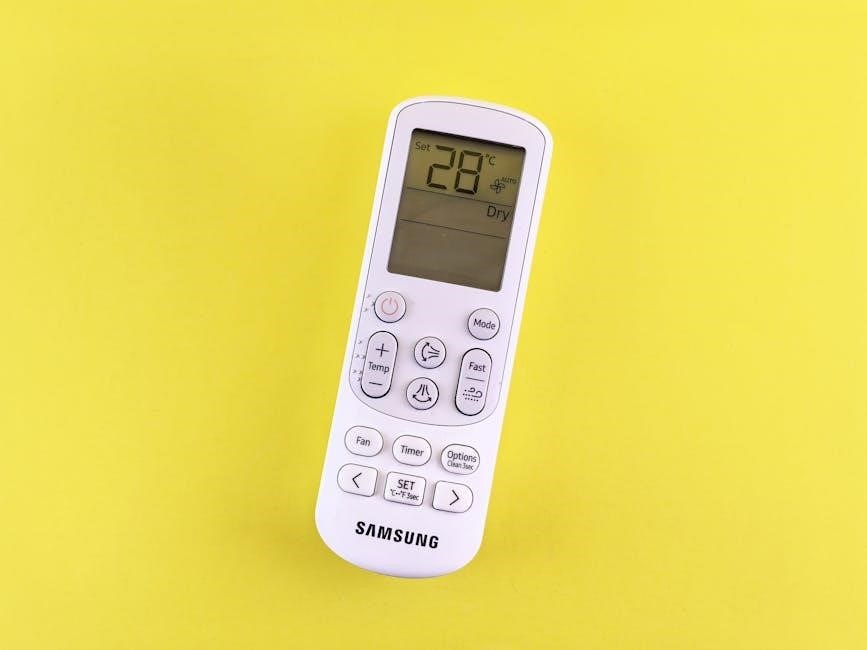
Remote Controller Display and Interface
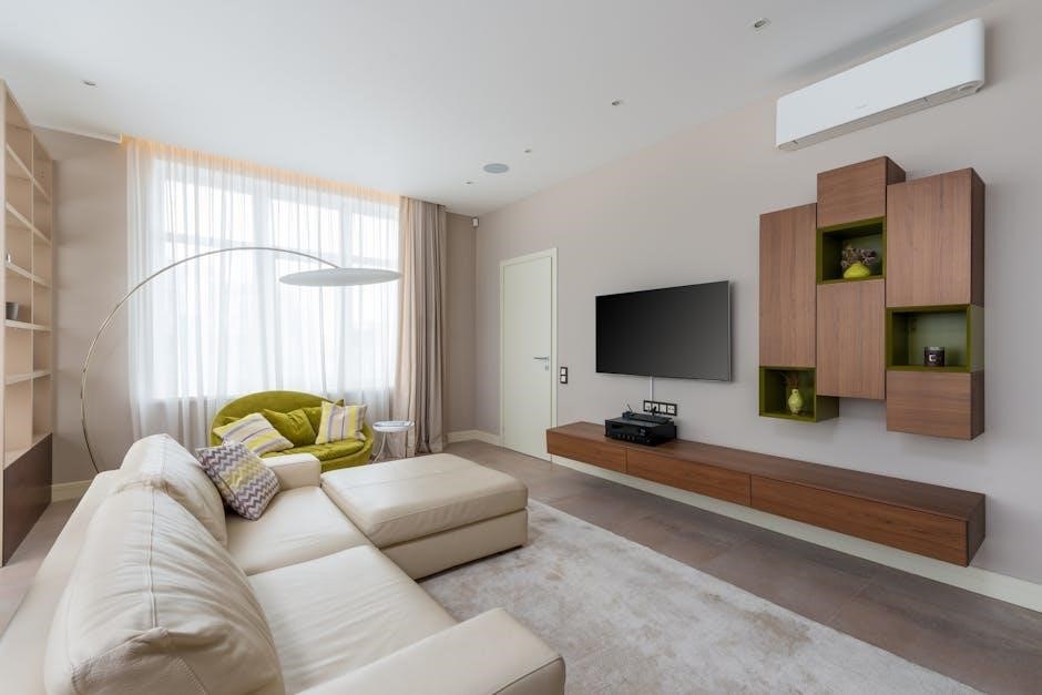
Daikin zone controllers boast an intuitive and user-friendly interface, enhanced by a clear, backlit display. This design prioritizes ease of use, allowing for effortless control of your ducted air conditioning system. The backlit display ensures excellent visibility, even in low-light conditions, making it simple to view and adjust controller functions.
The interface provides access to all essential settings, including temperature adjustments, fan speed control, mode selection, and timer programming. Its advanced design offers flexibility in installation, enabling placement in a location of your choosing for optimal convenience. The controller’s layout is logically organized, ensuring a seamless and efficient user experience, maximizing comfort and control.

Troubleshooting Common Issues
Addressing electrical wiring problems and controller power failures are crucial steps; carefully review installation guidelines to prevent electric shock or fire hazards.
Electrical Wiring Issues
Carefully inspect all wiring connections for tightness and proper insulation, ensuring adherence to the wiring diagram. Loose connections are a primary cause of operational failures, potentially leading to intermittent functionality or complete system shutdown. Verify that all field wiring passes correctly through the black plastic wiring bushes located at the bottom of the controller box, preventing strain and damage to the wires.
Confirm correct polarity and voltage levels are supplied to the controller, referencing the unit’s specifications. Incorrect voltage can cause immediate damage. If using optional connection leads like the Daikin KRCSO1-1, ensure the cut plug is correctly installed. Always prioritize safety; disconnect power before inspecting or correcting any wiring issues to avoid electrical shock. A qualified technician should address complex wiring problems.
Controller Not Powering On
If the controller fails to power on, begin by verifying the main power supply to the system is active and delivering the correct voltage. Check the circuit breaker and any associated fuses. Inspect all electrical wiring connections, ensuring they are secure and free from corrosion, paying close attention to those passing through the wiring bushes. Confirm the wiring polarity is correct, as reversed polarity can prevent operation.
Consider the initial setup; ensure the system clock and date are correctly configured, as some controllers require this for proper functionality. If the issue persists, consult the wiring diagram to confirm all connections are accurately made. A qualified technician should be consulted if the problem remains unresolved, as internal component failure may be the cause.