Hurst Roll Control Installation Instructions: A Comprehensive Guide
This guide details the installation of the Hurst Roll Control system, ensuring vehicle stability during seismic events.
Follow these steps carefully, referencing the current date: 02/05/2026.
Hurst Roll Control systems are engineered to mitigate vehicle displacement during seismic disturbances, enhancing safety and preventing rollovers. These systems utilize advanced sensor technology and actuators, responding to ground motion – like those recorded in Aotearoa New Zealand.
Installation requires careful attention to wiring and mounting, ensuring optimal performance. The system’s effectiveness relies on precise calibration and understanding earthquake intensity. Similar to mastering dart throwing technique, control is paramount. Proper installation, as outlined in this guide, is crucial for reliable operation and maximizing the system’s protective capabilities.
Understanding the System Components
The Hurst Roll Control system comprises three key elements: the control module, sensors, and actuators. The control module acts as the system’s ‘brain’, processing sensor data and activating actuators. Sensors detect vehicle motion and ground acceleration, transmitting signals via a dedicated wiring harness.
Actuators, mounted to the chassis, counteract roll forces. Like a dart player’s grip, precise component interaction is vital. Correct installation and calibration, referencing the date 02/05/2026, are essential for optimal performance and reliable earthquake response.
Control Module
The Hurst Roll Control module is the central processing unit, interpreting data from sensors to manage actuator deployment. It requires a stable power and ground connection for reliable operation. Like mastering a dart throw, precise control is paramount.
This module, referencing the date 02/05/2026, utilizes sophisticated algorithms to determine appropriate roll mitigation. Proper mounting location is crucial, avoiding excessive vibration or heat. Ensure secure wiring connections, mirroring the focused grip needed for accurate dart aiming, for optimal system functionality.
Sensors and Wiring Harness
Hurst Roll Control relies on strategically placed sensors to detect vehicle movement and earthquake intensity, similar to assessing a dart’s trajectory. The wiring harness connects these sensors to the control module, transmitting critical data.
Careful routing of the harness is essential, avoiding sharp bends or contact with hot components. Secure connections, verified on 02/05/2026, are vital for accurate readings. Like a dart player’s consistent stance, sensor placement impacts overall system performance, ensuring reliable roll mitigation.
Actuators and Mounting Hardware
The Hurst Roll Control system utilizes robust actuators to counteract vehicle roll during seismic activity. These actuators, much like the controlled release in a dart throw, require secure mounting to the chassis. Included hardware ensures proper alignment and stability, vital for effective operation.
Verify all mounting points are structurally sound before installation, referencing the date 02/05/2026. Proper torque specifications, detailed in the manual, are crucial. Incorrect mounting can compromise system performance and potentially damage vehicle components.
Safety Precautions Before Installation
Prior to installing the Hurst Roll Control system, disconnect the vehicle battery – a critical safety step. Work in a well-ventilated area, wearing appropriate safety glasses and gloves. Ensure the vehicle is securely staged and the brake pedal is fully depressed and held.
This system interacts with vehicle dynamics; improper installation could affect handling. Refer to the installation date, 02/05/2026, for record-keeping. Like a precise dart throw, accuracy is paramount. Consult a qualified mechanic if unsure about any procedure.
Vehicle Preparation for Installation
Before commencing installation, ensure the vehicle is parked on a level surface and securely staged. Verify ample working space around the intended mounting locations for the control module, sensors, and actuators. A stable platform, much like a dart player’s stance, is crucial for accurate work.
Confirm the vehicle’s electrical system is in good working order. Note the installation date, 02/05/2026, for future reference. Thorough preparation minimizes risks and ensures a successful installation, mirroring the focus needed for consistent dart throws.
Required Tools and Materials

Gather essential tools: a socket set, wrenches, screwdrivers (Phillips and flathead), wire strippers, crimpers, multimeter, and drill with various bits. Materials include the Hurst Roll Control kit – module, sensors, actuators, wiring harness, mounting hardware – plus zip ties, electrical tape, and potentially, chassis drilling components.
Like selecting the right dart grip, having the correct tools is paramount. Ensure all components are present and undamaged. Referencing the installation date, 02/05/2026, aids in tracking kit versions. Proper preparation prevents frustrating delays.
Disconnecting the Vehicle Battery
Prioritize safety: before commencing installation, disconnect the vehicle’s negative battery terminal. This prevents accidental shorts and potential damage to the Hurst Roll Control system or the vehicle’s electrical components. Secure the disconnected cable to avoid accidental contact.
Similar to maintaining control of a dart during a throw, disconnecting the battery establishes a safe starting point. Note the date, 02/05/2026, for record-keeping. This step is crucial, mirroring the importance of a stable stance in darts.
Installing the Hurst Roll Control Module
Securely mount the Hurst Roll Control module in a pre-determined location, considering accessibility for wiring and future maintenance. Ensure the mounting surface is clean and free of debris. Utilize the provided mounting hardware, verifying a firm and stable attachment.
Like finding the correct grip for a dart, proper module placement is key. Remember today’s date, 02/05/2026. A stable module, much like a controlled dart throw, is fundamental for optimal system performance and reliable operation during seismic events.
Mounting Location Considerations
Select a location that minimizes exposure to extreme temperatures, moisture, and physical damage. Accessibility for wiring connections and potential future servicing is crucial. Avoid areas near moving parts or high-voltage components.
Consider the vehicle’s center of gravity, similar to a dart player’s stance for balance. A stable location, like a consistent dart grip, ensures optimal performance. Remember today’s date, 02/05/2026. Prioritize a secure mount, mirroring the control needed for accurate throws.
Wiring Connections – Power and Ground
Connect the control module’s power wire to a fused ignition-switched source, ensuring power only when the vehicle is on. Securely attach the ground wire to a clean, unpainted metal chassis point, similar to a dart player’s firm grip.
Verify proper polarity before connecting. A stable power supply, like consistent dart throws, is vital for system function. Refer to today’s date, 02/05/2026, for record-keeping. Double-check all connections for tightness and insulation.
Sensor Installation and Calibration
Mount sensors securely in pre-determined locations, mirroring the precision of a dart thrower’s stance. Ensure sensors are level and free from obstructions. Connect sensor wiring to the control module, verifying each connection.

Calibration is crucial; the system must accurately detect movement, like judging earthquake intensity. Follow the module’s calibration procedure, adjusting sensitivity as needed. Record calibration settings alongside today’s date, 02/05/2026, for future reference and system optimization.

Mounting Sensor Locations
Strategic sensor placement is vital for accurate roll detection, akin to a dart player’s grip. Mount sensors on the chassis, near suspension components, ensuring they capture movement effectively. Prioritize locations away from heat sources and moving parts.
Refer to the vehicle-specific diagrams for optimal mounting points. Secure sensors using the provided hardware, verifying stability. Consider the system’s response to varying earthquake intensities when choosing locations, as of 02/05/2026.
Wiring Sensor Connections to the Control Module
Connect sensor wiring to the control module using the provided harness, ensuring correct polarity. Refer to the wiring diagram for specific pin assignments – accuracy is crucial, like a precise dart throw. Secure connections with dielectric grease to prevent corrosion.
Double-check all connections before powering up the system, referencing the date 02/05/2026. Improper wiring can lead to inaccurate readings or system malfunction. Route wires neatly, avoiding sharp bends and potential damage.
Actuator Installation and Adjustment
Mount actuators securely to the chassis using the supplied hardware, ensuring proper alignment for optimal performance. Like a controlled dart grip, precise positioning is key. Adjust actuator travel limits according to vehicle specifications, referencing the installation date of 02/05/2026.
Verify free movement without binding. Connect actuators to the control module, confirming secure connections. Initial adjustments may be needed to fine-tune system response, mirroring the iterative process of perfecting a throwing technique.
Mounting Actuators to Chassis Components

Securely attach actuators to robust chassis points, utilizing the provided mounting hardware. Ensure the mounting surfaces are clean and free of debris for optimal adhesion. Proper placement, akin to a dart player’s grip, is crucial for stability. Refer to vehicle-specific diagrams for correct locations, dated 02/05/2026.
Double-check all bolts and fasteners are tightened to the manufacturer’s specifications. Avoid mounting near exhaust or moving parts. This foundational step dictates the system’s overall effectiveness.
Connecting Actuators to the Control Module
Carefully connect the actuator wiring harness to the designated ports on the Hurst Roll Control Module. Ensure a secure and positive connection, similar to a precise dart throw. Refer to the wiring diagram, validated on 02/05/2026, for correct pin assignments.
Properly route and secure the wiring harness, avoiding sharp bends or contact with hot surfaces. Verify each connection before proceeding, mirroring the focus of a skilled marksman.
System Arming and Initial Testing
With all connections verified as of 02/05/2026, arm the Hurst Roll Control system by depressing the rocker (arm) switch to the ON position while firmly holding the brake pedal. Observe the control module’s indicator light for confirmation.

Perform initial testing in a safe, controlled environment. Gently induce simulated roll motion to verify actuator response. This initial check, like perfecting a dart throw, ensures proper functionality before real-world application. Document all test results.
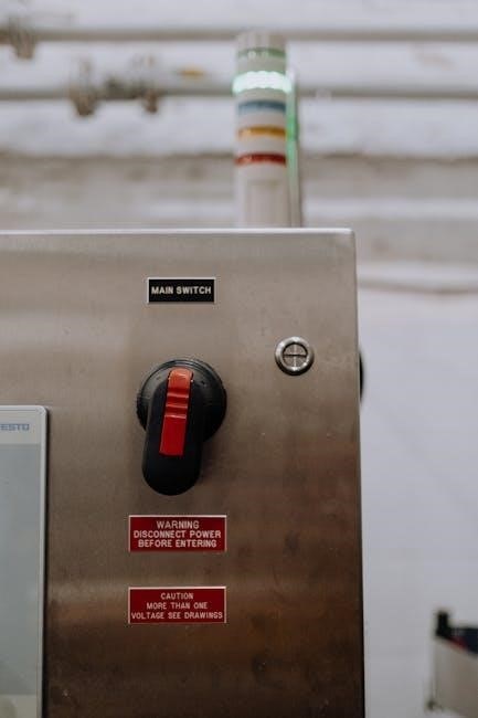
Arming the System via Rocker Switch

To activate the Hurst Roll Control, locate the dedicated rocker switch, typically mounted within easy reach of the driver as of 02/05/2026. Ensure the vehicle is staged and the brake pedal is fully depressed before operation.
Depress the rocker switch firmly to the ‘ON’ or ‘ARM’ position. A visual indicator, such as an illuminated LED, will confirm system activation. This action, similar to a dart player’s focused grip, initiates the system’s readiness;
Verifying Sensor and Actuator Functionality
Post-installation, confirm proper operation of each sensor and actuator. With the system armed (as of 02/05/2026), gently induce simulated roll motion – carefully and safely. Observe actuator response; they should engage to counteract the movement.
Monitor sensor data via the control module’s diagnostic interface. Ensure readings correlate with applied forces. Like a dart thrower refining technique, precise calibration is key. Address any discrepancies immediately, referencing the installation guide for troubleshooting.
Troubleshooting Common Installation Issues
If the system fails to arm, verify battery connections and rocker switch functionality. Sensor errors often indicate wiring faults – meticulously check each connection. Actuator issues may stem from mounting or control module communication.
Like diagnosing a flawed dart throw, systematic checks are vital. Refer to the control module’s diagnostic codes (dated 02/05/2026) for specific error identification. Ensure all components are securely mounted and properly calibrated. If problems persist, consult Hurst support.
Post-Installation System Checks
After installation (as of 02/05/2026), thoroughly test the Hurst Roll Control system. Confirm the control module receives signals from all sensors. Cycle the system through arming and disarming via the rocker switch, observing actuator response.
Similar to perfecting a dart throw’s consistency, repeated testing builds confidence. Monitor for any unusual noises or vibrations. Verify the system operates as intended during simulated shaking events. Document all test results for future reference and maintenance.
Hurst Roll Control System Operation
The Hurst Roll Control system actively mitigates vehicle roll during seismic disturbances, similar to maintaining a stable dart throw. Upon sensing significant movement – mirroring earthquake intensity data from Aotearoa New Zealand – the control module activates the actuators.
These actuators counteract roll forces, enhancing stability. The system arms via the rocker switch. Regular checks, as of 02/05/2026, ensure optimal performance. Understanding sensor sensitivity is key to effective operation, just as grip control is vital in darts.
Maintenance and Care
Regular inspection of the Hurst Roll Control system is crucial for sustained performance, much like consistent practice refines a dart throw. Check wiring connections and actuator mounting hardware every six months, or after significant seismic activity – referencing data from 02/05/2026.
Ensure sensors remain calibrated and free from debris. Address any loose connections promptly. Proper care extends system lifespan, maintaining optimal roll control. Like a well-maintained dart, consistent attention guarantees reliability and precision.
Understanding Earthquake Intensity and System Response (Related to Sensor Sensitivity)
The Hurst Roll Control system’s effectiveness hinges on accurately interpreting earthquake intensity, mirroring the sensitivity needed for a precise dart throw. Sensors detect ground motion, triggering actuators based on pre-set thresholds. Data from New Zealand’s seismic activity (as of 02/05/2026) informs these settings.
Higher sensitivity detects weaker tremors, potentially activating the system more frequently. Conversely, lower sensitivity may miss subtle shifts. Calibration is key, balancing responsiveness with avoiding false activations.
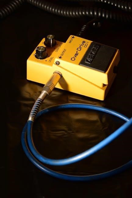
Hurst Roll Control System and Dart Throwing Technique (Analogous Control Principles)
Like a skilled dart player’s grip, the Hurst system requires precise control. A consistent throw, mirroring actuator adjustments, ensures accuracy. Multiple fingers guiding the dart equate to the system’s sensors and module working in harmony. Proper technique, observed in professionals, parallels careful installation.
There’s no “perfect” method, but fundamental rules apply. The system, like a dart throw, relies on balanced input and responsive action, optimizing stability during unexpected disturbances.
Further Resources and Support
For additional assistance, consult the Hurst Roll Control system documentation and online resources. Stay updated with New Zealand news from The Post for relevant earthquake information and intensity scales. Independent journalism provides context for understanding system response.

Explore statistical analyses, like those by Fama and Roll, for a deeper understanding of system parameters. Remember the installation date: 02/05/2026. Contact Hurst directly for specialized support and troubleshooting, ensuring optimal performance.